
Relations
ATLAS.ti allows you to establish named links to more clearly express the nature of the relationships between concepts. With named links, you may express a sentence like "a broken leg causes pain" by two nodes (the source node "broken leg" and the target node "pain") connected with a named link ("causes" or "is-cause-of").
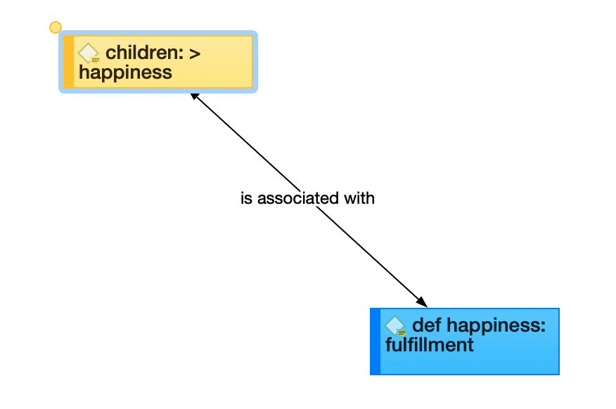
The name of a link is displayed in the network editor as a label attached to the link midway between the two connected nodes.
Six pre-set relations are available in ATLAS.ti. These standard relations can be substituted, modified, or supplemented by user-defined relations.
Link vs. Relation
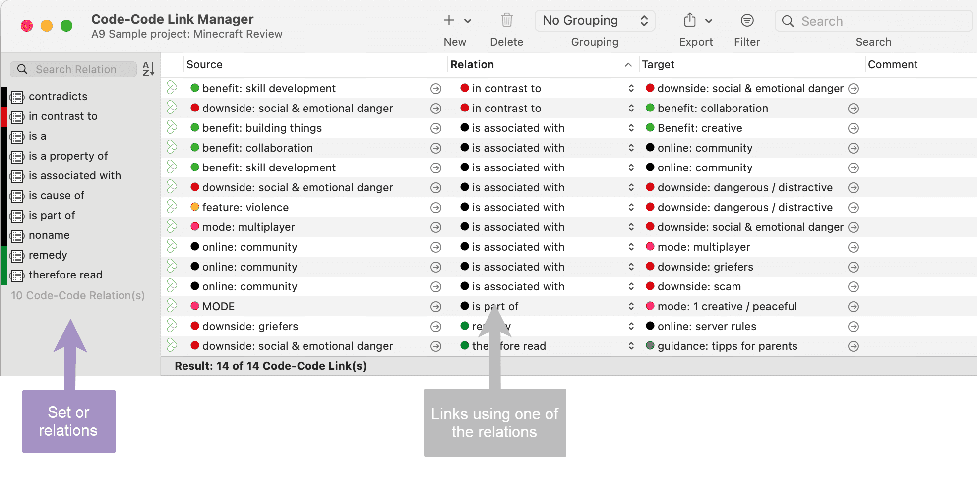
It is important to understand the difference between a relation (or a link type), and the link itself: There is only one "is part of" relation, but potentially many links that can use it.
If you take a look at the Code-Code Link Manager below, you can easily see how it works:
 Another way to think of links and relations is to view links as instances of relations. Links are informed about the characteristics of relations, which define their styles. If a characteristic of a relation is changed (e.g., line width, color, symbol), these changes are propagated to all links using it.
ATLAS.ti Default Relations
The default relations that come with the software are listed in the table below. C1 and C2 are source and target nodes, respectively.
| Relation Name | short name | symbolic name | width | color | property |
|---|---|---|---|---|---|
| is associated with | R | == | 1 | Black | Symmetric |
| is part of | G | [] | 1 | Black | Asymmetric |
| is cause of | N | => | 1 | Black | Asymmetric |
| contradicts | A | <> | 1 | Black | Symmetric |
| is a | Isa | 0 | 2 | Black | Asymmetric |
| noname | 1 | Black | Symmetric | ||
| is property of | P | *} | 1 | Black |
Some of these characteristics directly affect the display of links, while others affect processing (e.g., search routines, automatic layout). A link between concepts is displayed in a network editor by a line with the relation's label. You can choose from three different labels (name, short and symbolic).
 The relation property affects the display a relation. All asymmetric relations are symbolized in the network editor with an arrow pointing toward the target code. Symmetric relations are displayed as a line with two arrows pointing to both ends of the link.
The following properties are user-definable: the labels, the width and color of the line linking two nodes, the property, and the preferred layout direction.
The preferred layout direction affects the layout of a network when opening an ad hoc network.
Formal Properties - Some Definitions
Symmetric Relationship
A relation R is symmetric if it holds for all A and B that are related via R. A is related to B if, and only if, B is related to A.
Examples:
- A is married to B (in most legal systems)
- A is a fully biological sibling of B
- A is a homophone of B
QDA Examples:
- walking the talk is associated with role model
- having a clear vision is related to performance orientation
- communicating well is associated with empowerment
Asymmetric Relations
A graph is asymmetric if:
- for every edge, there is not an edge in the other direction, then the relation is asymmetric
- loops are not allowed in an asymmetric digraph
If x has a relation R to y, but y does not have a relation R to x.
Examples:
- Martin is a child of Marilyn: If Martin is the child of Marilyn, then Marilyn cannot be the child of Martin.
QDA Examples:
If we use the same example as above, but instead define the relation results in being an asymmetric one, then you do not infer that nice weather is necessarily related to you being a happy person, or that you being a happy person has any effect on the weather. The later would be the case if you used a symmetric relation.
The relations in the following example are defined as asymmetric relations: Supportive environment motivates learning & development results in higher job satisfaction. This does not imply that a supportive environment results in higher job satisfaction.