
Network Editor - Layout And Routing Options
You can select among twelve automatic layout options. The results of the automatic layout procedure are typically quite usable and provide a good starting point for subsequent manual refinement. They can be combined with four routing options that are responsible for an optimal placement of the links.
The Layout and routing options are available from the Network Editor via the main Network Tab, and the View Tab. By moving nodes to different positions, you can modify an initial layout created by the automatic layout procedure. For precision placement of nodes, use the Grid and Snap option under the View Tab.
Layout Options
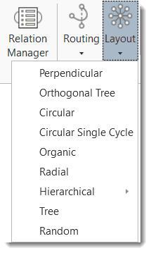
Perpendicular Layout: Orthogonal layouts allow the edges of the graph to run horizontally or vertically, parallel to the coordinate axes of the layout. It produces compact drawings with no overlaps, few crossings, and few bends.
Orthogonal Tree Layout: Same as the standard perpendicular layout, but larger subtrees are processed using a specialized tree layout algorithm, which is better suited for tree-like structures.
Circular Layout: The circular layout places the nodes on a circle, choosing carefully the ordering of the nodes around the circle to reduce crossings and place adjacent nodes close to each other. It emphasizes group and tree structures within a network. It creates node partitions by analyzing the connectivity structure of the network, and arranges the partitions as separate circles. The circles themselves are arranged in a radial tree layout fashion. This algorithm suits social network analysis quite well.
Circular Single Cycle Layout: This is similar to the circular layout, only subgroups are not created and all nodes are placed on a single circle. Useful for creating an overview and for shallow hierarchies.
Organic Layout: The organic layout style is based on the force-directed layout paradigm. When calculating a layout, the nodes are considered to be physical objects with mutually repulsive forces, like, e.g., protons or electrons. The connections between nodes also follow the physical analogy and are considered to be springs attached to the pair of nodes. These springs produce repulsive or attractive forces between their end points if they are too short or too long. The layout algorithm simulates these physical forces and rearranges the positions of the nodes in such a way that the sum of the forces emitted by the nodes, and the edges reaches a (local) minimum. Resulting layouts often expose the inherent symmetric and clustered structure of a graph, they show a well-balanced distribution of nodes and have few edge crossings.
Radial Layout: When applying the radial layout style, the nodes of a graph are arranged on concentric circles. The layout calculation starts by conceptually reducing the graph to a tree structure whose root node is taken as the center of all circles. Each child node in this tree structure is then placed on the next outer circle within the sector of the circle that was reserved by its parent node. All edges that were initially ignored are re-established, and the radii of the circles are calculated taking the sector sizes needed by each whole subtree into account. This layout style is well suited for the visualization of directed graphs and tree-like structures.
Hierarchical Layout: The hierarchical layout style aims to highlight the main direction or flow within a directed graph. The nodes of a graph are placed in hierarchically arranged layers such that the (majority of) edges of the graph show the same overall orientation, for example, top-to-bottom. Additionally, the ordering of the nodes within each layer is chosen in such a way that the number of edge crossings is small.
-
Hierarchical Layout (Top-Bottom): Prefers to place nodes downwards from top to bottom along directed links.
-
Hierarchical Layout (Bottom-Top): Prefers to place nodes upwards from bottom to top along directed links.
-
Hierarchical Layout (Left-Right): Prefers to place nodes from left to right along directed links.
-
Hierarchical Layout (Right-Left): Prefers to place nodes from right to left along directed links.
Tree Layout: The tree layout is designed to arrange directed and non-directed trees that have a unique root node. All children are placed below their parent in relation to the main layout direction. A child-parent relation in ATLAS.ti is defined via a transitive. Before applying the layout all nodes compromising a strict tree are removed and added after the tree layout by connecting them with curved edges. Tree layout algorithms are commonly used for visualizing relational data. The layout algorithm starts from the root and recursively assigns coordinates to all tree nodes. In this manner, leaf nodes will be placed first, while each parent node is placed centered above its children.
Random Layout: Randomly places the nodes every time this layout is invoked.
Routing
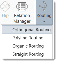
The positions of the nodes in the network are not altered by rerouting the edges.
Orthogonal Routing: This is a versatile and powerful layout algorithm for routing a diagram's edges using vertical and horizontal line segments only. The positions of the diagram's nodes will remain fixed. Usually, the routed edges will not cut through any nodes or overlap any other edges.
Poly Line Edge Routing: Polyline edge routing calculates polyline edge paths for a diagram's edges. The positions of the nodes in the diagram are not altered by this algorithm. Edges can be routed orthogonally, i.e., each edge path consists of horizontal and vertical segments, or octilinear. Octilinear means that the slope of each segment of an edge path is a multiple of 45 degree.
Organic Routing: This algorithm routes edges organically to ensure that they do not overlap nodes and that they keep a specifiable minimal distance to the nodes. It is especially well suited for non-orthogonal, organic or cyclic layout styles.
Straight Routing: Draw the links between nodes as straight lines without any consideration of node and edge crossing.
The routing layout is not saved. If you close the network and open it again, the routing is lost, and you have to select a routing option again. If you are happy with the layout and want to keep the network as it, you need to export it.